

LQ-CO katalytické spalovací zařízení
Cat:Zařízení
Přehled Katalytické spalování je metoda čištění, která používá katalyzátory k oxidaci a rozkládání hořlavých látek ve výfukových plynech př...
Viz podrobnosti
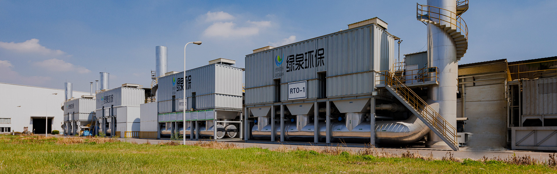
The right organic waste gas treatment equipment for a facility depends mainly on three factors: the exhaust air volume, the concentration of volatile organic compounds (VOCs) in the gas stream, and whether energy recovery or solvent recovery matters for the process. For large air volumes with medium to low VOCs concentration, regenerative thermal oxidizers (RTO) or heat-storage catalytic incineration equipment (RCO) are commonly selected because they combine high destruction efficiency with substantial thermal energy recovery. For smaller air volumes with high VOCs concentration, direct-fired high-temperature incineration equipment, often called a TO furnace, tends to be a better fit because it achieves rapid, thorough combustion without the added complexity of a heat-storage bed. For large air volumes with low concentration organic waste gas, a zeolite rotary concentrator is frequently paired with an oxidation unit so the pollutant load is concentrated first, which reduces the size of the downstream oxidizer.
This article reviews the main categories of organic waste gas treatment equipment, including high-temperature incineration systems, catalytic combustion and heat-storage catalytic incineration units, zeolite adsorption and concentration equipment, gas-to-gas heat exchangers for energy recovery, and solid waste incineration furnaces that complement gas-phase treatment. Typical performance characteristics reported in industry technical literature are presented through charts and a reference table to help engineering teams compare technologies on a consistent basis. A practical decision framework is also included so that facility managers and environmental engineers can match organic waste gas treatment equipment to real site conditions rather than general assumptions.
Organic waste gas is generated whenever solvents, resins, coatings, inks, adhesives, or other volatile compounds are used or heated during manufacturing. Typical sources include printing and coating lines, chemical and pharmaceutical synthesis, electronics assembly, packaging, rubber and plastics processing, and food or flavor production. When released untreated, these emissions contribute to ground-level ozone formation and can carry an unpleasant odor, which is why environmental authorities in most industrialized regions have progressively tightened permissible emission limits for VOCs and related pollutants over the past decade, a trend widely documented in environmental engineering guidance and industry technical literature.
Selecting suitable organic waste gas treatment equipment starts with characterizing the exhaust stream rather than choosing a technology first. The parameters below generally drive the decision between thermal destruction, catalytic destruction, and physical adsorption or recovery:
Once these parameters are known, organic waste gas treatment equipment can generally be grouped into three technology paths that are discussed in the following sections: high-temperature thermal incineration, catalytic combustion with or without heat storage, and adsorption-based concentration and recovery systems that are frequently combined with an oxidation stage for final destruction.
High-temperature incineration equipment destroys VOCs by raising the exhaust gas to a temperature high enough for thorough thermal oxidation, converting organic compounds into carbon dioxide and water vapor. Within this category, the way heat is managed after combustion is what separates the main equipment types.
LQ-RTO heat-storage high-temperature incineration equipment, commonly known as a regenerative thermal oxidizer, uses ceramic heat-storage media arranged in alternating beds. Incoming waste gas passes through a bed that has already been heated by the previous combustion cycle, so the gas is preheated before it reaches the combustion chamber, and the hot treated gas then passes through a second bed to store heat for the next cycle. This regenerative exchange is what allows the equipment to recover a large share of the combustion heat internally, which is particularly valuable for large air volume, medium and low concentration organic waste gas that would otherwise require continuous supplementary fuel.
LQ-RRTO rotary heat-storage high-temperature incineration equipment applies the same regenerative principle but uses a rotating heat-storage structure instead of switching valves between fixed beds. The rotary design simplifies the airflow path and reduces the equipment footprint, which makes it a practical option where plant space is limited but the process still requires efficient heat recovery for large or fluctuating air volumes.
The LQ direct-fired high-temperature incineration purification equipment, generally referred to as a TO furnace, sends waste gas directly into a combustion chamber without cycling it through a heat-storage bed first. This more straightforward configuration is well suited to high concentration, small air volume exhaust streams, where rapid and complete combustion decomposition is the priority and the simpler airflow path can be an operational advantage. A supplementary heat exchanger can still be added downstream to recover part of the heat for preheating incoming air.
Figure 1 below is an illustrative isometric schematic of a regenerative thermal oxidizer arrangement, intended to show the general airflow concept rather than a specific engineering drawing.
In this simplified schematic, waste gas enters from the left and first passes through a heat-storage bed that was heated during the prior cycle, which preheats the gas before it reaches the combustion chamber shown at the top center of the housing. Inside the combustion chamber, the preheated gas is raised to the oxidation temperature required for complete VOCs destruction. The hot, treated gas then flows through the second heat-storage bed, transferring its heat to the ceramic media so that energy is available for the next incoming batch of gas. Flow direction through the two beds is periodically reversed by a set of switching valves, which is the mechanism that gives regenerative thermal oxidizers their high internal heat recovery. Once the treated gas has given up most of its heat, it exits through the clean gas stack shown on the right side of the diagram.
The chart below compares typical thermal energy recovery efficiency across the main incineration and catalytic combustion technologies, based on general engineering characteristics documented in industry technical literature on VOCs abatement systems.
This column chart illustrates why regenerative designs are generally preferred for large, continuous air volumes with medium or low VOCs concentration. Regenerative thermal oxidizers and rotary regenerative units, shown as RTO and RRTO, typically recover a very large share of the combustion heat because the ceramic storage media directly preheats each incoming batch of gas. Heat-storage catalytic incineration equipment, shown as RCO, achieves comparably high recovery because it applies the same regenerative principle at a lower oxidation temperature. Catalytic combustion equipment without heat storage, shown as CO, and direct-fired TO furnaces without a heat-storage bed generally show lower internal heat recovery, which is why they are more often matched to smaller air volumes or higher concentration streams where continuous heat recovery is less critical. These figures are typical, illustrative ranges reported in industry engineering literature and can vary depending on specific equipment design, insulation, and operating conditions.
Catalytic combustion equipment uses a catalyst bed to lower the temperature required for VOCs oxidation, which reduces auxiliary fuel demand compared with pure thermal incineration. This category is generally suited to medium and low concentration exhaust gas where the presence of a catalyst allows destruction to take place at a substantially lower operating temperature.
LQ-CO catalytic combustion equipment passes preheated waste gas through a catalyst bed where oxidation occurs at a lower temperature than direct thermal incineration, which reduces fuel consumption while still achieving thorough VOCs destruction. This equipment is generally appropriate for medium and low concentration organic waste gas where the reduced operating temperature offers a practical operating advantage.
LQ-RCO heat-storage catalytic incineration equipment combines the lower operating temperature of catalytic oxidation with a regenerative heat-storage structure similar in principle to an RTO. This combination allows the equipment to achieve both a lower oxidation temperature and a high level of internal thermal efficiency, making it a suitable option for large air volume, medium and low concentration organic waste gas where energy efficiency and destruction performance both matter.
The horizontal bar chart below compares the typical oxidation operating temperature range required by each incineration and catalytic combustion technology.
This horizontal bar chart highlights the operating temperature gap between catalytic and purely thermal technologies, which is the main reason catalyst-based equipment can offer meaningful fuel savings. Catalytic combustion and heat-storage catalytic incineration equipment generally operate in a considerably lower temperature band, typically in the range of roughly three hundred to four hundred and twenty degrees Celsius, because the catalyst lowers the activation energy needed for VOCs oxidation. Regenerative thermal oxidizers and direct-fired TO furnaces, by comparison, generally require temperatures well above seven hundred degrees Celsius to achieve complete thermal destruction without catalytic assistance. The relatively narrow temperature band required by catalytic equipment also tends to translate into lower refractory and insulation demands. As with all technology comparisons in this article, the exact operating temperature for a given installation depends on the specific VOCs composition, required destruction efficiency, and equipment design, so these ranges should be treated as general, typical values rather than fixed specifications.
The LQ-ADW zeolite rotating drum, sometimes described as a cylinder-type zeolite concentrator, is designed for large air volume streams where the VOCs concentration is too low to sustain efficient direct incineration. The rotating drum is packed with hydrophobic zeolite molecular sieve material that continuously adsorbs organic compounds as the low concentration waste gas passes through a large section of the wheel. A smaller portion of the wheel is simultaneously regenerated using a separate, much smaller volume of hot air, which desorbs the collected VOCs into a concentrated stream. Because this concentrated stream carries a much smaller air volume at a substantially higher VOCs concentration, it can then be sent to a smaller oxidizer, such as an RTO, RCO, or CO unit, for final destruction, which is generally more energy efficient than treating the full original air volume directly.
This concentrate-then-oxidize approach is one of the more widely adopted strategies for organic waste gas treatment equipment serving industries such as printing, coating, and packaging, where exhaust air volumes are large but VOCs concentration per cubic meter is relatively low. In addition to the rotating drum concentrator, the same equipment lineup also includes gas heat exchangers and integrated purification units that recover energy and combine several treatment stages, which are discussed in the following sections.
The LQ-TT-CO gas heat exchanger recovers thermal energy from the hot, treated exhaust leaving an incineration or catalytic combustion unit and uses it to preheat the incoming waste gas or combustion air. This gas-to-gas heat exchange reduces the amount of supplementary fuel a system needs to maintain its target oxidation temperature, and it is commonly integrated alongside RTO, RCO, CO, and TO furnace equipment as part of a complete organic waste gas treatment equipment package rather than sold only as a standalone accessory.
As VOCs concentration in the incoming gas rises, the heating value carried by the organic compounds themselves increases, and at a sufficiently high concentration the combustion process can become largely self-sustaining, meaning supplementary fuel demand approaches a minimum. The relationship is illustrated qualitatively in the line chart below.
This line chart shows the general downward relationship between waste gas VOCs concentration and the amount of supplementary fuel an incineration system needs to maintain its target temperature. At very low concentration, the heating value of the organic compounds contributes little energy, so the oxidizer or heat exchanger must supply most of the heat needed for destruction. As concentration rises toward what is often called the near-autothermal or near-self-sustaining point, the combustion heat released by the VOCs themselves increasingly offsets the energy requirement, and supplementary fuel demand declines accordingly. Beyond this point, at sufficiently high concentration, the process can approach full self-sustaining combustion with minimal or no additional fuel. Gas heat exchangers such as the LQ-TT-CO help shift a facility toward this favorable end of the curve at any given concentration by recovering and reusing heat that would otherwise be lost with the treated exhaust. The exact position of the autothermal point depends on the specific VOCs composition, calorific value, and the design of the equipment, so this chart should be read as an illustrative relationship rather than a fixed value for any particular installation.
Organic waste gas treatment processes often generate solid by-products alongside the treated exhaust stream, including spent activated carbon, filter residues, and other solid waste that must be disposed of properly. The LQ-SWI solid waste incineration furnace provides onsite capability for handling this solid waste, reducing the volume that needs to be transported offsite and giving a facility a more complete environmental management approach that addresses both gas-phase and solid-phase waste streams. Pairing gas-phase organic waste gas treatment equipment with a solid waste incineration furnace is particularly relevant for facilities using adsorption media, such as activated carbon or zeolite, that eventually requires replacement and disposal after repeated adsorption and regeneration cycles.
No single type of organic waste gas treatment equipment is best suited to every situation, since each technology involves a different balance between energy recovery, physical footprint, and the air volume or concentration range it handles well. The radar chart below offers a qualitative, relative comparison across three common configurations: a regenerative thermal oxidizer, a heat-storage catalytic incineration unit, and a zeolite rotor concentrator paired with an oxidizer.
This radar comparison is intended to show relative strengths rather than precise measured values. The regenerative thermal oxidizer scores highly on energy recovery and on suitability for large, continuous air volumes, reflecting its internal ceramic heat-storage exchange, but scores lower on compact footprint and on handling high concentration streams, where a simpler direct-fired approach is usually more appropriate. Heat-storage catalytic incineration equipment follows a broadly similar pattern to the regenerative thermal oxidizer, since it uses the same regenerative principle, though its lower oxidation temperature can offer some footprint and fuel advantages. The zeolite rotor paired with an oxidizer stands out for its strength in handling large air volumes at low concentration and for its adsorption and recovery capability, since the rotor itself is compact relative to the air volume it can process, though it depends on a downstream oxidizer for final destruction of the concentrated stream. Facility teams should treat these scores as a general starting point for technology screening rather than a substitute for a proper engineering evaluation of a specific waste gas stream.
The table below summarizes general application ranges for the main organic waste gas treatment equipment models discussed in this article, based on typical industry practice.
| Model | Technology | Typical Air Volume | Typical Concentration | Key Characteristic |
|---|---|---|---|---|
| LQ-RTO | Regenerative thermal oxidation | Large | Medium to low | High internal heat recovery |
| LQ-RRTO | Rotary regenerative thermal oxidation | Large | Medium to low | Compact rotary heat exchange |
| LQ TO furnace | Direct-fired thermal oxidation | Small | High | Rapid, thorough combustion |
| LQ-CO | Catalytic combustion | Medium | Medium to low | Lower oxidation temperature |
| LQ-RCO | Heat-storage catalytic incineration | Large | Medium to low | Heat recovery plus catalysis |
| LQ-ADW | Zeolite rotating drum concentration | Large | Low | Concentrates gas before oxidation |
| LQ-TT-CO | Gas-to-gas heat exchange | Any, paired with oxidizer | Any | Recovers exhaust heat |
| LQ-SWI | Solid waste incineration | Not applicable | Not applicable | Handles solid by-products onsite |
A structured evaluation process helps engineering teams narrow down organic waste gas treatment equipment options before committing to a detailed design. The following steps outline a general approach that applies across most industrial exhaust gas treatment projects.
Across many regions, environmental authorities have moved toward progressively stricter limits on VOCs and odorous emissions from industrial sources, a direction reflected in national environmental protection guidance and technical standards for waste gas treatment. This regulatory trend, combined with rising energy costs for industrial processes, has encouraged wider adoption of combined process configurations, such as pairing zeolite rotor concentration with an oxidizer, or pairing a regenerative thermal oxidizer with a gas heat exchanger, because these arrangements tend to offer a favorable balance between destruction efficiency and energy consumption. Industry technical literature on VOCs abatement also points to continuing interest in heat-storage catalytic incineration equipment as a way to combine lower operating temperatures with strong thermal efficiency for large air volume applications. Facilities planning new or upgraded organic waste gas treatment equipment are generally well served by reviewing current local emission standards early in the design process, since permissible limits and monitoring requirements can differ meaningfully between regions and over time.
Lvquan Environmental Protection Engineering Technology Co., Ltd. is located in the city of Gaoyou, Yangzhou, the north gate of Jiangsu. It is a joint-stock enterprise established through cooperation among professionals with rich experience in VOCs equipment design and manufacturing spanning more than thirty years. The company operates as a professional manufacturer of organic waste gas treatment engineering equipment, with a registered capital of twenty two million yuan, fixed assets of nearly forty million yuan, total assets of nearly sixty million yuan, and a factory building area of nine thousand eight hundred square meters.
The company maintains more than two hundred sets of various types of machining equipment and a team of one hundred twenty employees, supporting an annual production capacity valued at one hundred million yuan. This manufacturing base supports the full organic waste gas treatment equipment lineup described in this article, spanning high-temperature incineration systems such as LQ-RTO, LQ-RRTO and the direct-fired TO furnace, catalytic combustion and heat-storage catalytic incineration equipment such as LQ-CO and LQ-RCO, zeolite adsorption and concentration equipment such as LQ-ADW, gas heat exchangers such as LQ-TT-CO, and solid waste incineration furnaces such as LQ-SWI.
Organic waste gas treatment equipment is used to remove or destroy volatile organic compounds from industrial exhaust streams before the air is released, typically through thermal or catalytic oxidation, or through adsorption and concentration ahead of a final destruction stage.
An RTO, or regenerative thermal oxidizer, destroys VOCs through pure thermal oxidation at a high temperature using ceramic heat-storage media. An RCO, or heat-storage catalytic incineration unit, uses a catalyst bed alongside the same regenerative heat-storage principle, which allows oxidation to occur at a lower temperature while still recovering a large share of the combustion heat.
A zeolite rotor, such as the LQ-ADW rotating drum, adsorbs VOCs from a large volume of low concentration gas and then desorbs them into a much smaller, more concentrated air stream during regeneration. This concentrated stream can then be treated by a smaller oxidizer, which is generally more energy efficient than treating the full original air volume directly.
Yes. Gas-to-gas heat exchangers, such as the LQ-TT-CO, recover thermal energy from the treated exhaust and use it to preheat incoming waste gas or combustion air, which reduces the amount of supplementary fuel needed to maintain the target oxidation temperature.
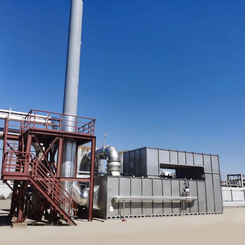
Přehled Katalytické spalování je metoda čištění, která používá katalyzátory k oxidaci a rozkládání hořlavých látek ve výfukových plynech př...
Viz podrobnosti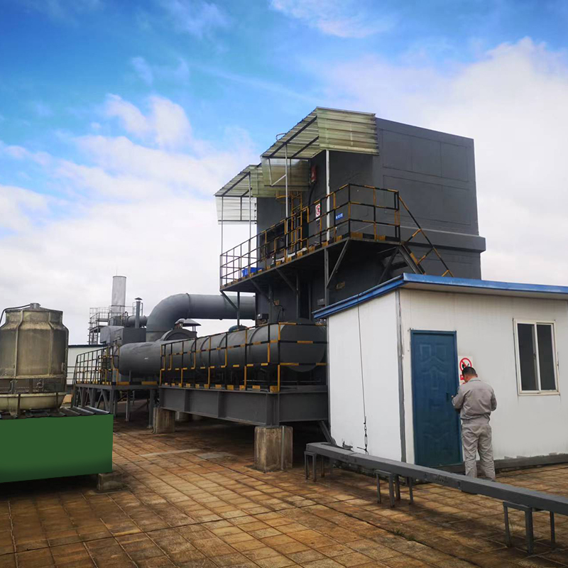
Přehled Katalytická oxidace tepelného skladování (regenerativní katalytický oxidační oxidační prostředky/RCO) je zařízení pro zpracování pl...
Viz podrobnosti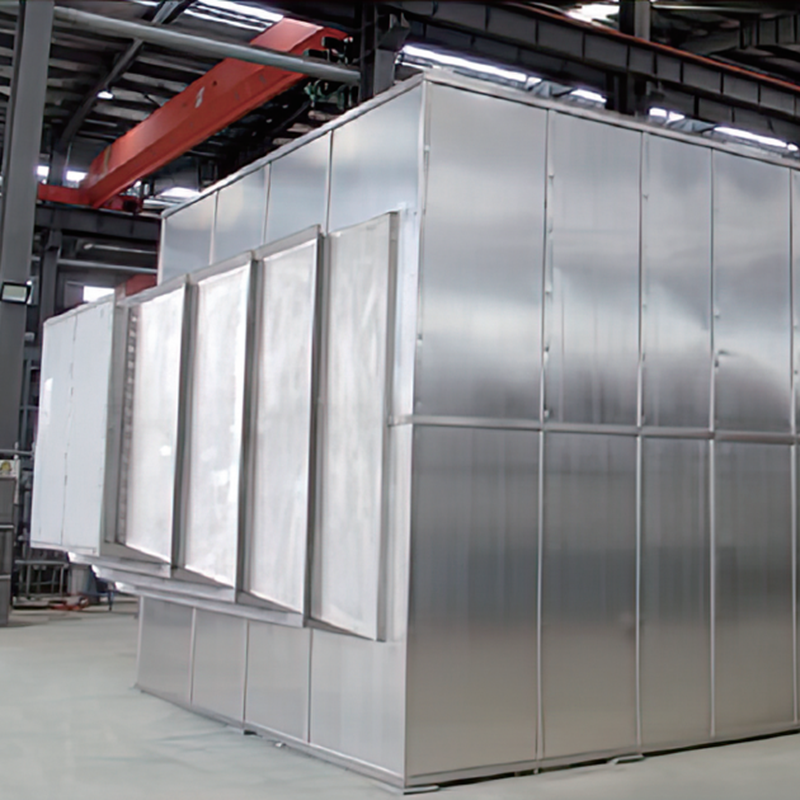
Úvod produktu Výměník plynového tepla se používá hlavně pro odvětví úspory energie a snižování emisí při regeneraci odpadního tepla v různý...
Viz podrobnosti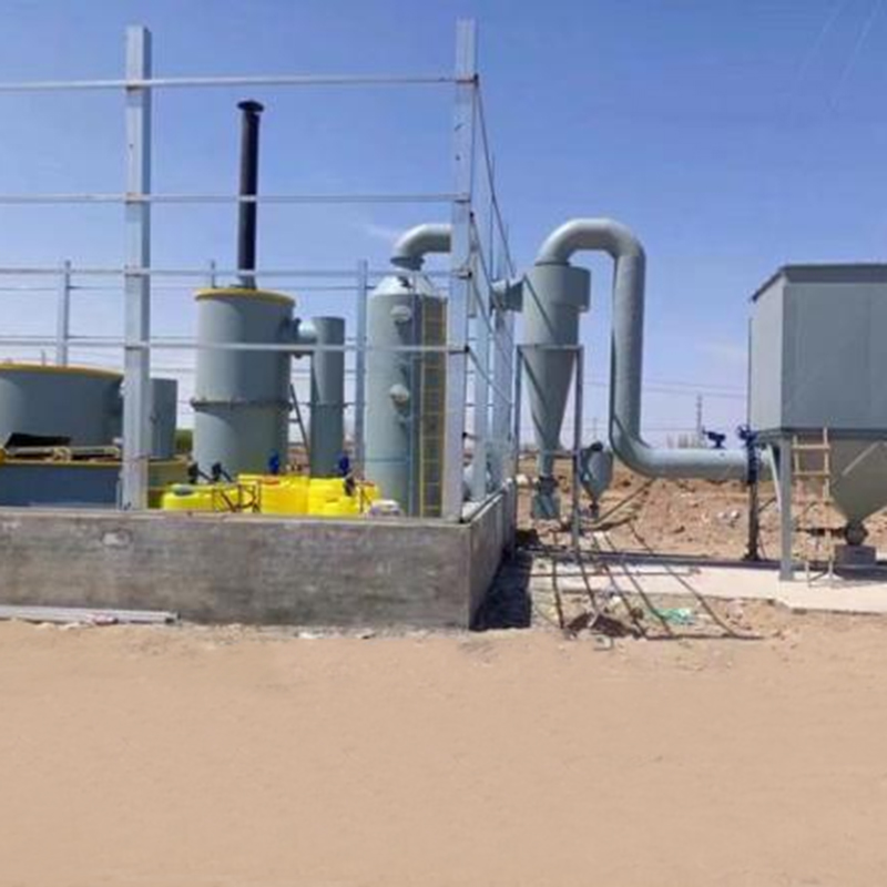
Přehled Spalovací pece na pevné odpady jsou nezbytným vybavením při řízení pevného odpadu, které jsou navrženy tak, aby transformovaly ...
Viz podrobnosti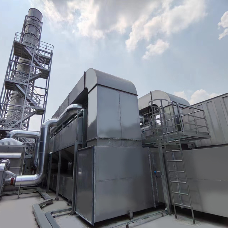
Přehled o zotavovacích zařízeních aktivovaných aktivovaných uhlíkových vláken Organické rozpouštědlo Aktivovaný systém pro zotavení čiš...
Viz podrobnosti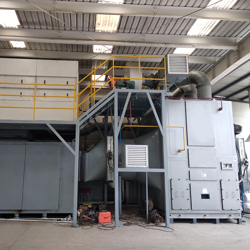
Koncept úplného souboru zařízení Účelem použití adsorpce rotačního bubnu seolitu pro plyn z organických odpadů je koncentrace nízkého konce...
Viz podrobnosti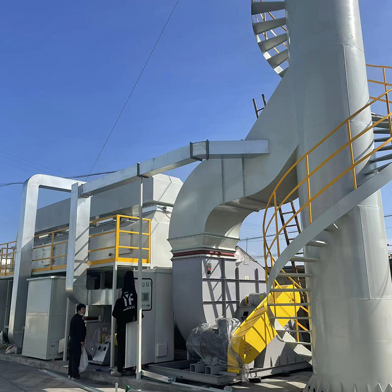
Voc-CFT-CO adsorpční katalytické čištění zařízení Adsorpční zařízení pro adsorpci VOC-CFT-CO, které se skládá z voštinového uhlíku s pevným...
Viz podrobnosti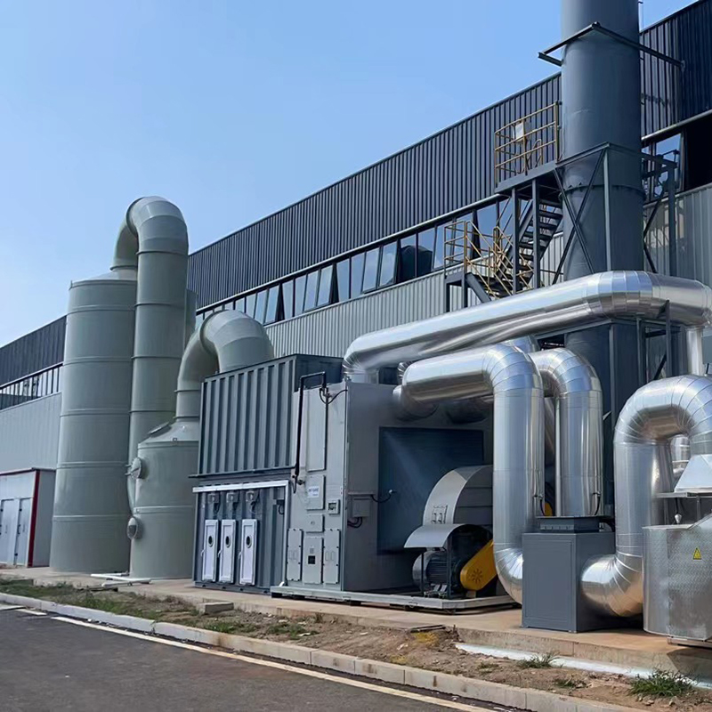
Koncept pevného postele zeolitu Katalytické spalování jako sada zařízení Spalovací zařízení pevného lože zeolitu je vhodné pro koncentraci ...
Viz podrobnosti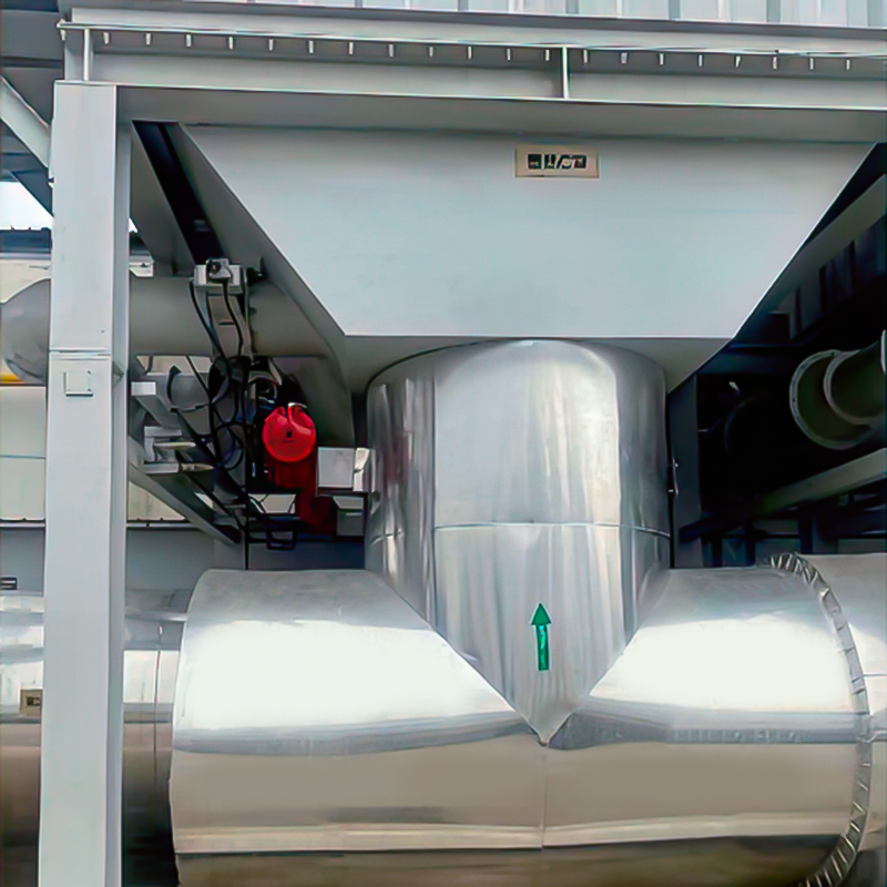
Účel Používá se hlavně pro proporcionální ventilaci vysokoteplotního kouřového plynu. LT se široce používá na místech, kde nejsou požadavky...
Viz podrobnosti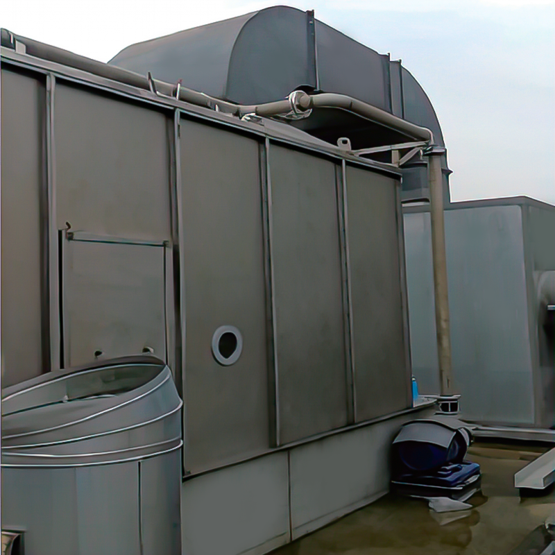
Přehled Princip odstraňování mokrého prachu používá proces zachycení a oddělení prachových částic v plynné fázi plně kontaktováním dvou fáz...
Viz podrobnostiMOBILNÍ


Copyright © LV Quan Environmental Protection Engineering Technology Co., Ltd. All Rights Reserved. VOCS ORGANICKÝ PLASOVÝ PLAV PŘIPOJENÍ ZAŘÍZENÍ ZAŘÍZENÍ

